Center Pivot Runtime, Flow & Application Depth Sizer
Compute system hydraulic delivery capacity, percent timer speed runtime, gross vs. net application depth, and full revolution rotation hours across standard and corner spans.
1. Machine Geometry & Hydraulics
Field SpecsEngineering Principles of Center Pivot Hydraulics, Revolution Timing & Uniformity
1. Kinematics of Radial Movement & Timer Percentages
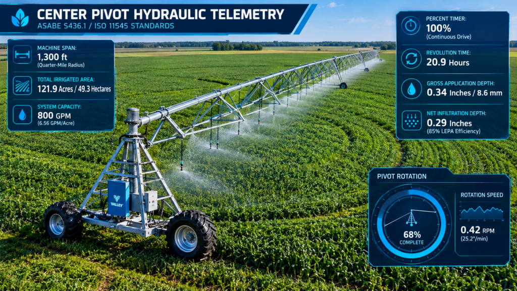
A center pivot irrigation machine pivots about a fixed central anchor pad while multiple mobile towers travel along concentric circular paths. The speed of each intermediate tower is mechanically governed by the outermost end-tower. Because circular perimeter distance expands proportionally with radius ($2 \pi R$), the last tower covers the greatest linear distance. Percent timers control the duration of running vs. resting cycles of the last tower (typically cycling over a 60-second baseline). At 100% timer setting, the end tower operates continuously without interruption, producing the fastest revolution time and the shallowest gross application depth.
2. Governing Mathematical Formulations (ASABE S436.1)
Gross application depth represents the volume of water discharged per unit of irrigated land area during a complete circle or sector revolution:
Net Depth (Inches) = Gross Depth × Application Efficiency (η)
Revolution Time (Hours) = [ 2 × π × Last_Tower_Radius (ft) ] / [ Speed_100% (ft/min) × (Timer_% / 100) × 60 ]
The coefficient 453 is the hydraulic volumetric conversion factor converting GPM-hours to acre-inches of depth ($1 \text{ Acre-Inch} = 27,154 \text{ Gallons}$). In metric terms, depth is calculated directly from total delivery volume in cubic meters divided by irrigated square meters ($1 \text{ mm} = 1 \text{ L/m}^2$).
3. Nozzle Sizing & Application Intensity Dynamics
A key physical challenge of center pivot irrigation is the non-linear distribution of water discharge along the span length. As radius $R$ expands, the annular area irrigated by a unit span of pipe increases quadratically. To maintain uniform application depth from pivot pad to outer wheel track, water discharge per foot of pipe must increase linearly from center to edge. Outer spans utilize significantly larger nozzle orifices and closer spacing, creating extreme instantaneous application rates (often exceeding 3 to 4 inches per hour) that can exceed soil infiltration rates on heavy clay or sloping terrain, inducing surface runoff and wheel track rutting.
4. Minimizing Evaporative & Wind Drift Losses
Modern center pivot design relies heavily on Low Elevation Spray Application (LESA) and Low Elevation Precision Application (LEPA) drop hose drops positioned 1 to 2 feet above the crop canopy. By operating at reduced pressures (10 to 20 PSI via inline regulators) and depositing water directly into furrows or low canopies, growers elevate operational application efficiencies from 70–75% (traditional high-pressure overhead impact sprinklers) to over 88–95%, drastically conserving pumping energy and water resources.