Tractor PTO Torque, Implement Power & Ballast Stability Sizer
Determine continuous PTO output torque, implement power consumption margins, drawbar reserve, and required front-axle ballast to eliminate steering light-off.
1. Tractor & Implement Parameters
2. Transmission & Ballast Verdict
OPTIMAL MATCHEngineering Principles of Tractor PTO Power, Shaft Torque, & Static Ballast
1. The Difference Between Gross Engine Power and PTO Horsepower
Tractor manufacturers prominently market gross flywheel engine power. However, mechanical parasitic loads—including transmission gear meshes, hydrostatic cooling pumps, cooling fans, and hydraulic steering circuits—consume substantial energy. According to standardized OECD and Nebraska Tractor Test benchmarks, actual available Power Take-Off (PTO) output ranges between 84% to 88% of gross engine rating on modern mechanical-front-wheel-drive (MFWD) tractors. Sizing an implement based directly on manufacturer flywheel specifications frequently results in engine bogging, excessive exhaust gas temperatures (EGT), and clutch plate glazing.
2. PTO Shaft Torque Dynamics: 540 RPM vs. 1000 RPM
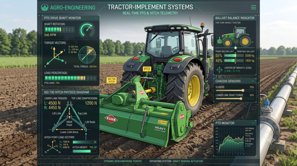
Rotary power transmission through a Cardan drive shaft is governed strictly by the relationship between rotational speed and angular torque:
Metric: Torque (N·m) = (PTO kW × 9549) / PTO RPM
Notice that running at 540 RPM requires nearly double the torque compared to 1000 RPM for the exact same horsepower output. This high-torque profile exerts severe shear stresses on implement gearboxes, universal joints, and slip clutches. High-inertia equipment such as large square balers, heavy-duty flail mowers, and stubble shredders should always utilize a 1000 RPM shaft configuration whenever available to halve mechanical driveline stress.
3. Three-Point Linkage Leverage and Dynamic Front-Axle Ballasting
When heavy implements (such as reversible moldboard plows, heavy disc harrows, or seed drills) are lifted via the Category 1, 2, or 3 three-point linkage, the tractor rear axle acts as a fulcrum point. According to ASABE S318 safety standards, a tractor must maintain at least 20% of its static gross tractor weight on the front steering axle under all transport conditions to ensure adequate braking friction and steering control.
Insufficient front ballasting leads to severe front-wheel bounce, loss of steering authority on road gradients, and premature failure of the rear axle final drives due to excessive vertical static cantilever loading. Conversely, over-ballasting causes parasitic soil compaction and excessive transmission parasitic draw in soft field conditions.